Cooling tower retrofit: cooling capacity increased
THE CHALLENGE
We are requested by Gases Oxinorte A.I.E, company that produces air gases, to increase the cooling capacity in its nitrogen liquefaction facility in Vizcaya.
Brief description of Oxinorte:
In the air separation unit (ASU) its components are fractionated by cryogenic distillation, obtaining liquid argon, O2 and N2 gas. Final products:
- Channeled Gas Oxygen: O2 is supplied by pipeline to surrounding steelworks.
- Liquid Argon -186ºC: from ASU, is stored in a tank for distribution.
- Liquid Nitrogen -196ºC (lin): It is produced in the N2 compression / expansion liquefaction facility. This lin is stored in a tank for distribution.
- Liquid Oxygen -183ºC (lox): The O2 gas is liquefied in an exchanger with part of the lin. It is stored in a tank for distribution.
- Medicinal Liquid Oxygen: it is manufactured according to the Pharmacopoeia from industrial lox
THE SOLUTION
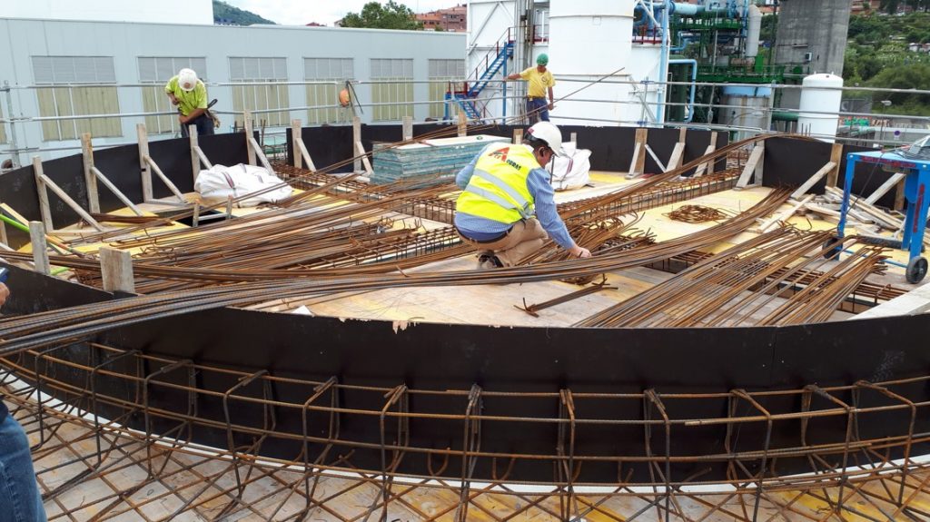
The civil works construction of a cell complementary to the existing cooling tower of 2 concrete cells of 10 x 12 meters with a total recirculation water flow of 2,250 m3 / h is proposed.
THE RESULT
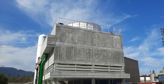
Torraval’s field erected cooling towers are designed under the principle of induced draft, working counter flow. In this case, OC serie, it consists of reinforced concrete structure, composed by pilars and beams system.
The concrete upper part of the field erected cooling tower consists on a platform where the mechanic equipment is pinned. In the centre, we place a GRP diffuser. In all the length of the side of water entry, we find the reinforced concrete major collector.
Air entries are located in the lower part along the entire perimeter. A partition wall is placed in the middle of the cooling tower and in perpendicular direction to air flow, whose role is to pulse the air and prevents the scape of water outside as a result of wind. The different cells have intermediate septums that extend from water normal level to fan cover, so that each cell can stay out of service without affecting the functioning of the others.
The aspirate air, goes across the cooling tower in counter-current to the with hot water that falls through the laminar filling. The water to be cooled enters on the collector by the entry pipe and spreads throughout the distribution system and nozzles, falling evenly on the filling. From there, it falls into the concrete collection basin.
COOLING TOWER’S INTERNAL PARTS
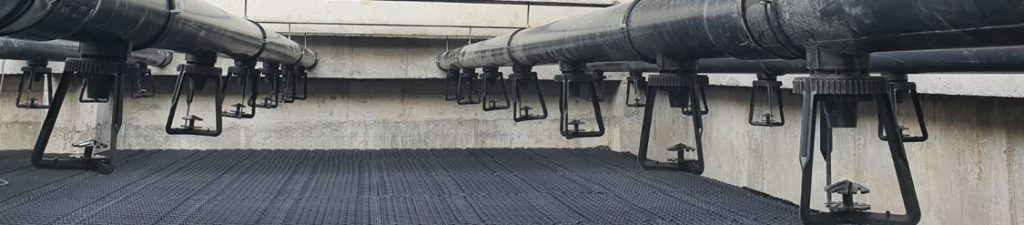
– Distribution system: water distribution system composed of a main concrete external channel and secondary pipes with nozzles that provides a perfect water distribution on the filling and easy maintenance.
– Drift eliminators: they consist of PVC set panels placed over the water distribution system, in order to collect drops that can be drag outside. They ensure any drift eliminator losses less than 0.002% of water flow circulation.
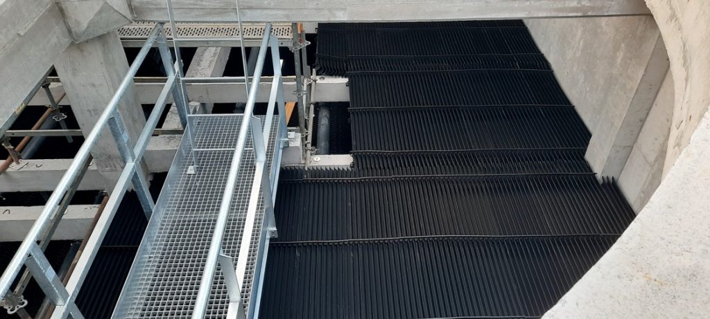
– Fill pack: thermal exchange between water and air is produced inside the fill pack. The cooling tower is equipped with laminar fill in PVC manageable blocks. The fill pack covers the entire inside cooling tower surface to prevent air coming from the lower part. The fill pack is placed in a grid above an air entry.
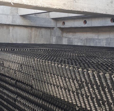
It has been taken into account that the industrial water was clean in the fill pack selection.
Also it has to be considered the dirt water circulation level, is the one from the contributed water multiplied by the system concentration cycles, adding additionally dust or dirt that the plant could have in suspension, or that water in contact with the cooling process could drag.
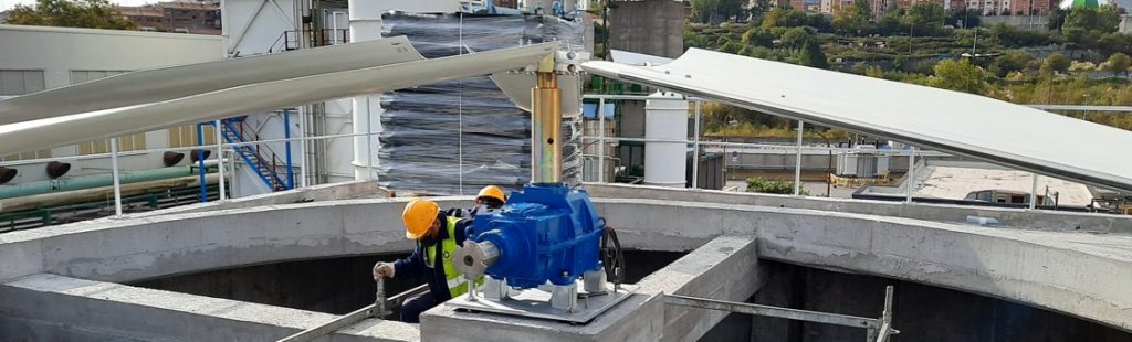
MECHANICAL EQUIPMENT
– Motor: Totally closed and self-vented, it is installed in the cover of the cooling tower out of the wet airflow
the power between motor and gear is transmitted through a floater shaft with flexible coupling in both extremes.
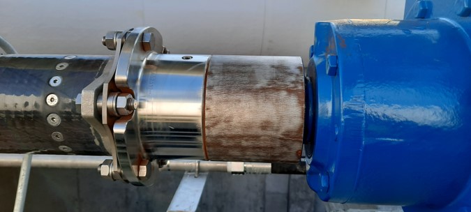
– Reducer: type helical conical, with non-return device, specially design for using in cooling towers. It is able to support the conditions of saturated wet air flow at the high temperature it leaves the cooling tower.
– Lubrication system: lubrication and grease of reducers are performed from outside of diffuser.
DIFUSSER
Make in GRP, designed to allow air output avoiding its recirculation. The lower part of the diffuser has a Venturi design, to minimize drop pressure. The upper part has tapered divergent shape, that allows to transform part of the kinetics energy of outgoing air into an increasing static pressure, which is the energetic consumption reduction.
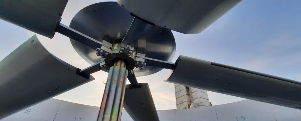
– Fan: axial type with aerodynamics form blades, brewed in GRP with adjustable blade angle.
ACCES, PLATAFORM AND GATES
The cooling tower is equipped with a cage ladder that leads to the upper platform where the fan is located. There are gates and ladders with direct access inside the cooling equipment that facilitate inspection and maintenance of mechanical tools, water distribution systems and drift eliminator.
CUSTOMER BENEFITS
The new cell increases efficiency-cooling water 3-4 grades more in the circuit .
